| The term IROC is the acronym for International Race of Champions. The concept of the IROC series was to identically prepare stock cars by a single team of mechanics in an effort to make the race purely a test of driver ability. If you would like to know more about IROC there are many articles on the webbernet. Anyway, this article is about building a set of IROC hot rods or as I refer to them IRODs. If you're interested in the building of the IROC hot rods then please click on the read more link. | 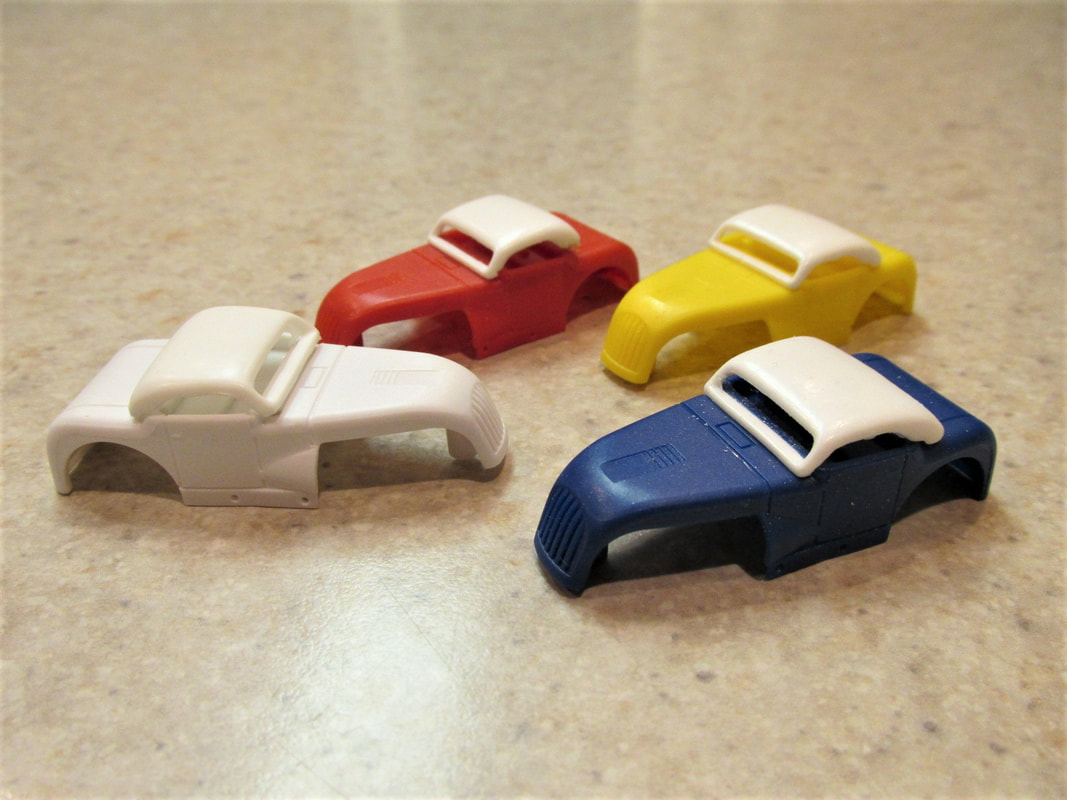 |
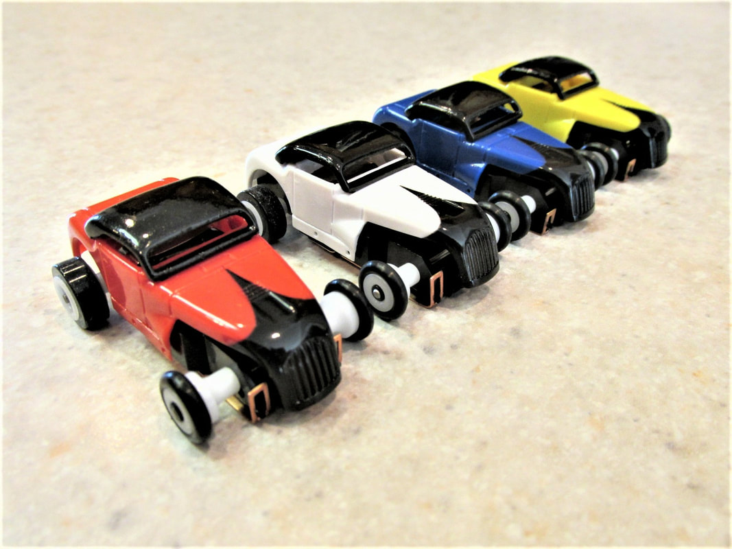
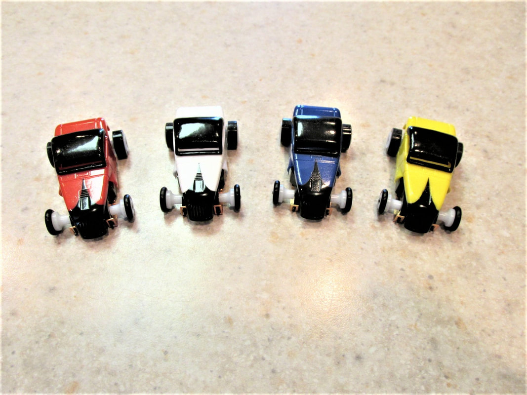
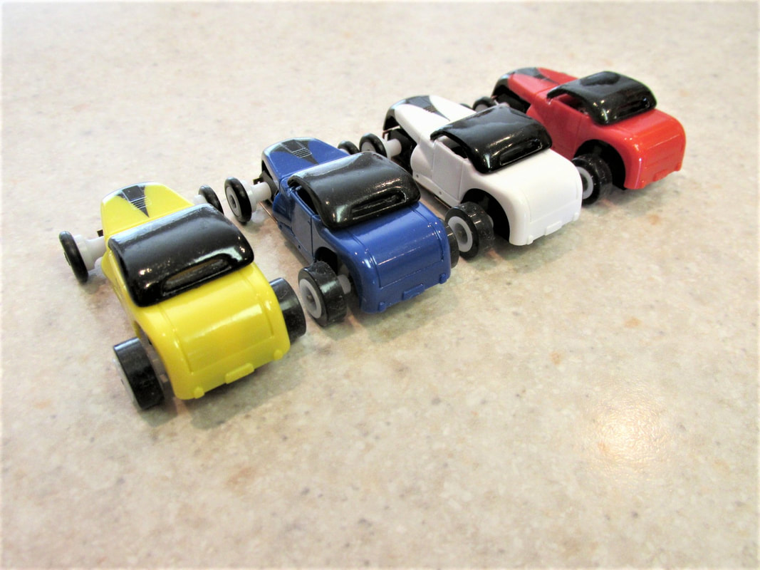
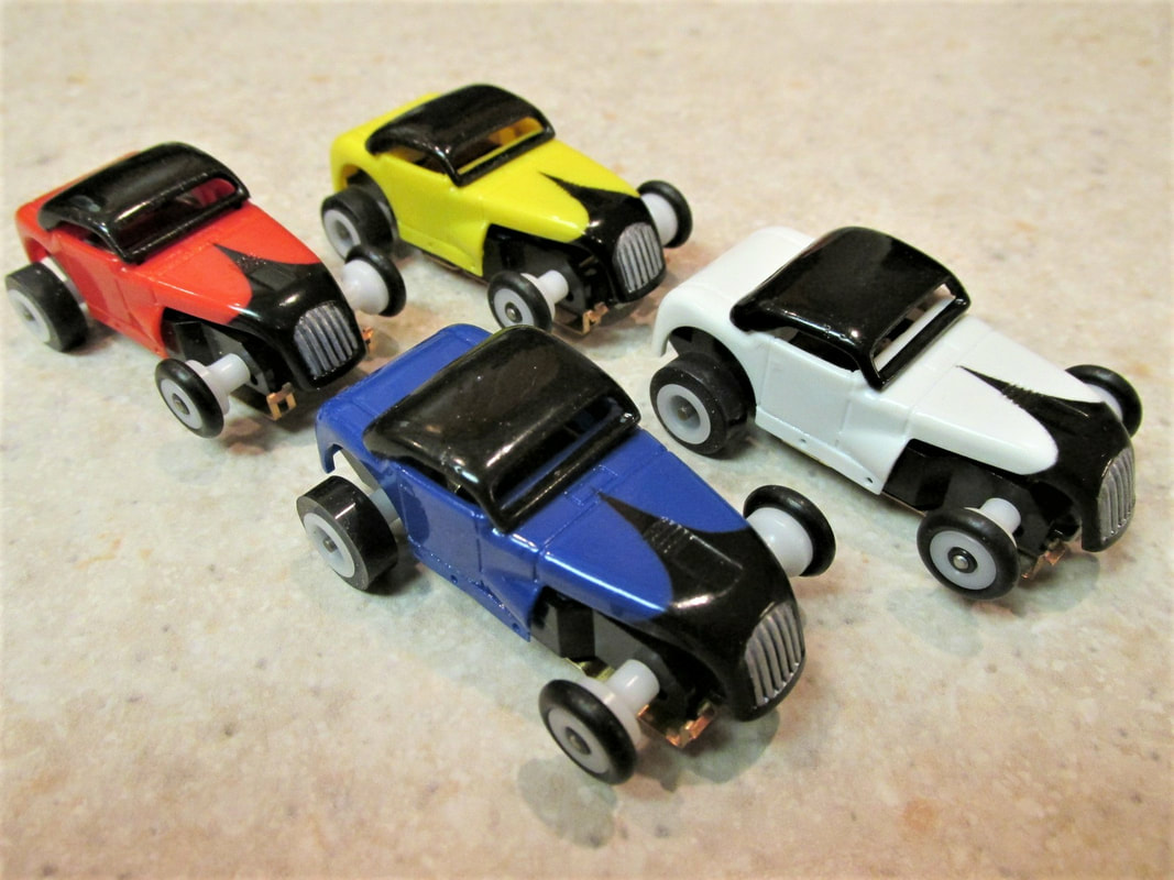
For this project I will be building 4 hot rods. I had 4 Dash chassis on hand and I ordered some Dash hot rod bodies. The usual colors for IROC bodies are white, yellow, red, and blue if your running on a 4 lane track. If it is a 6 lane track then you will need to add a green and orange car.
One other note on this build. All the cars will be very close in specifications how ever they will not be exactly alike. There will be slight variations in magnet strength, and armature ohms, however, they will be very close but not exactly the same. That said, it shouldn't matter that much due to the fact that each driver will drive all 4 cars during the race.
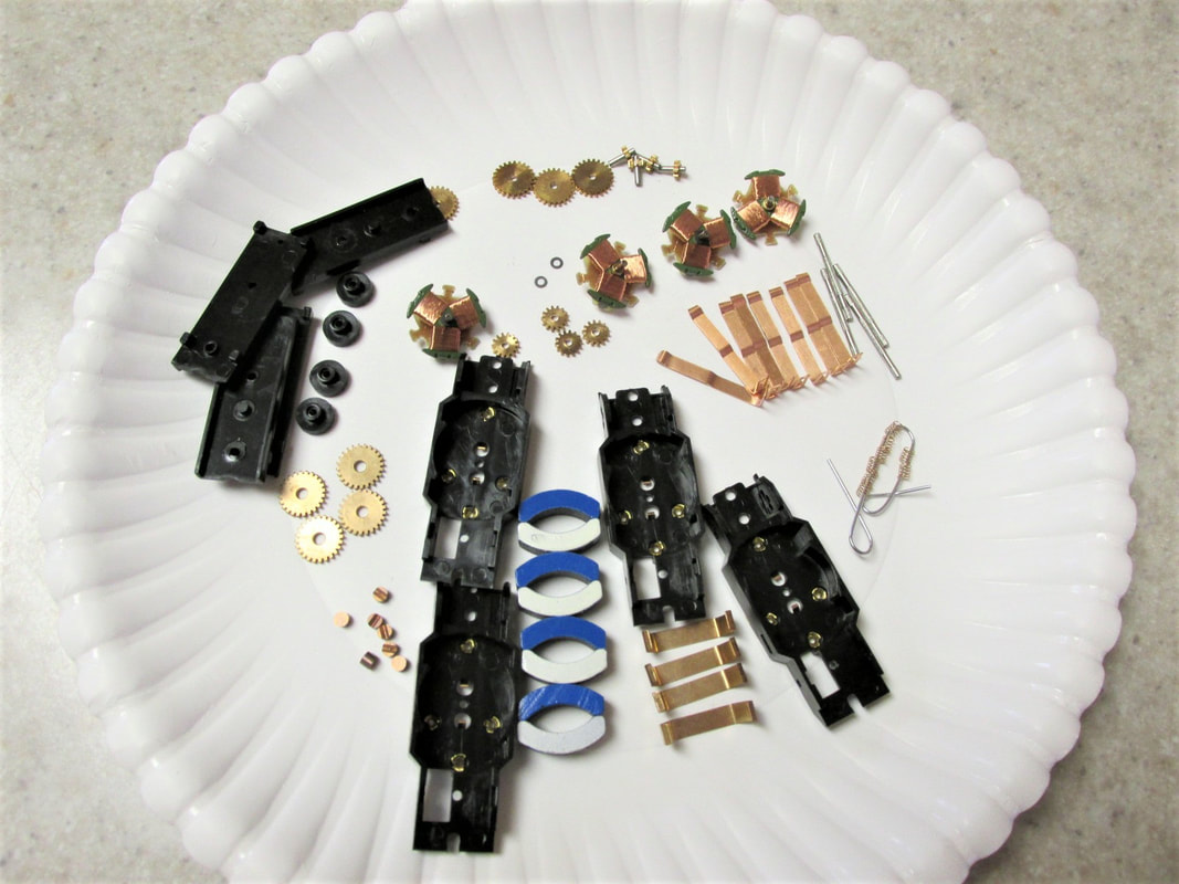
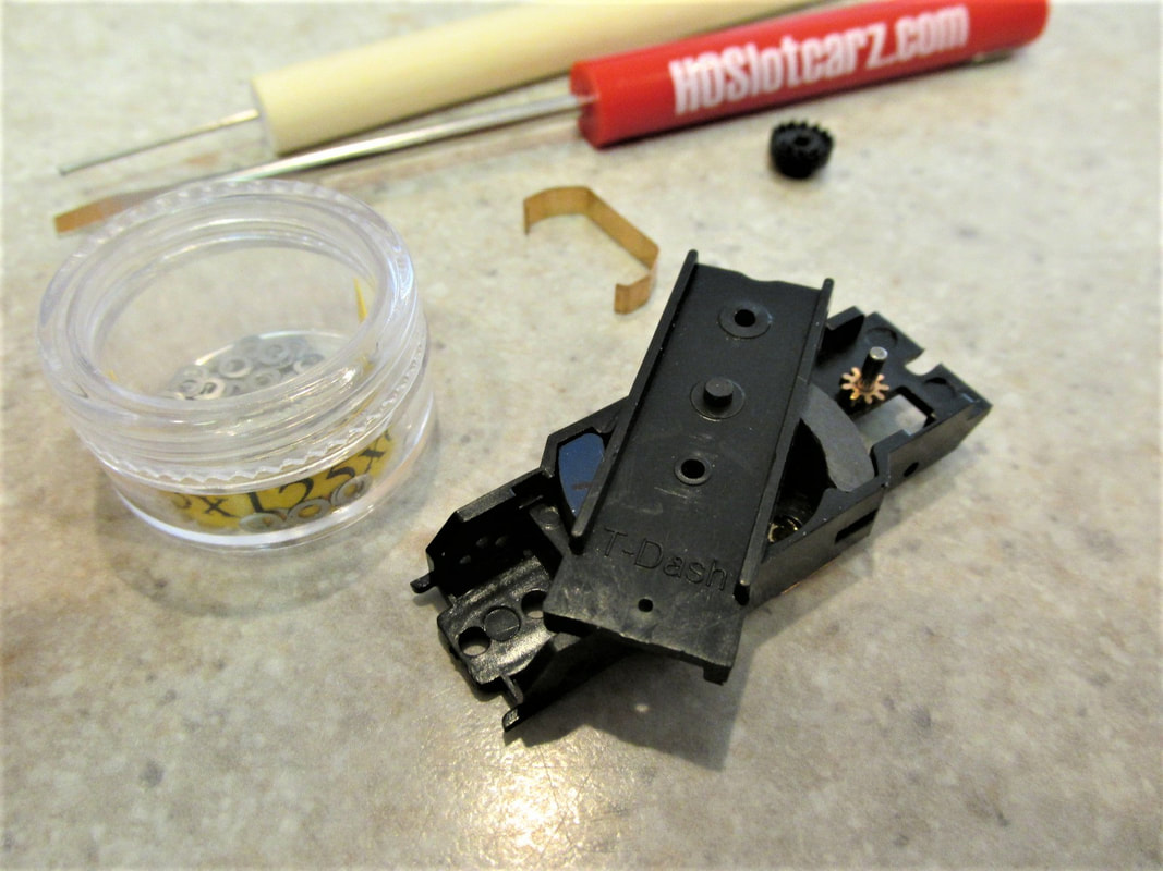
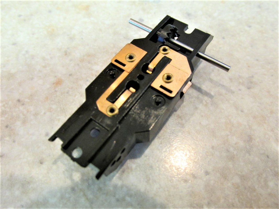
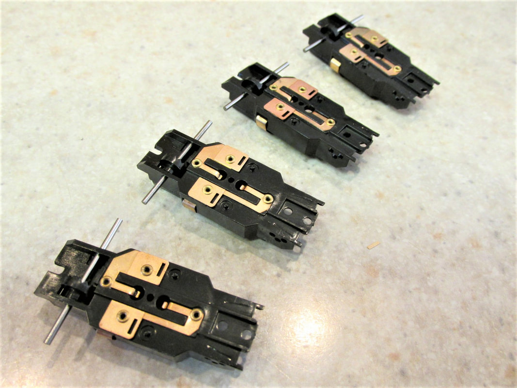
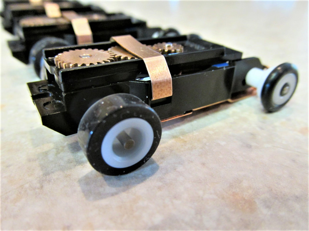
The 4 Dash chassis are the version 2 chassis that has the 16 ohm 2 lam armatures. The first thing I will do is to take them apart so I can tweak them as I rebuild them.
One other note on this build. All the cars will be very close in specifications how ever they will not be exactly alike. There will be slight variations in magnet strength, and armature ohms, however, they will be very close but not exactly the same. That said, it shouldn't matter that much due to the fact that each driver will drive all 4 cars during the race.
The 4 Dash chassis are the version 2 chassis that has the 16 ohm 2 lam armatures. The first thing I will do is to take them apart so I can tweak them as I rebuild them.
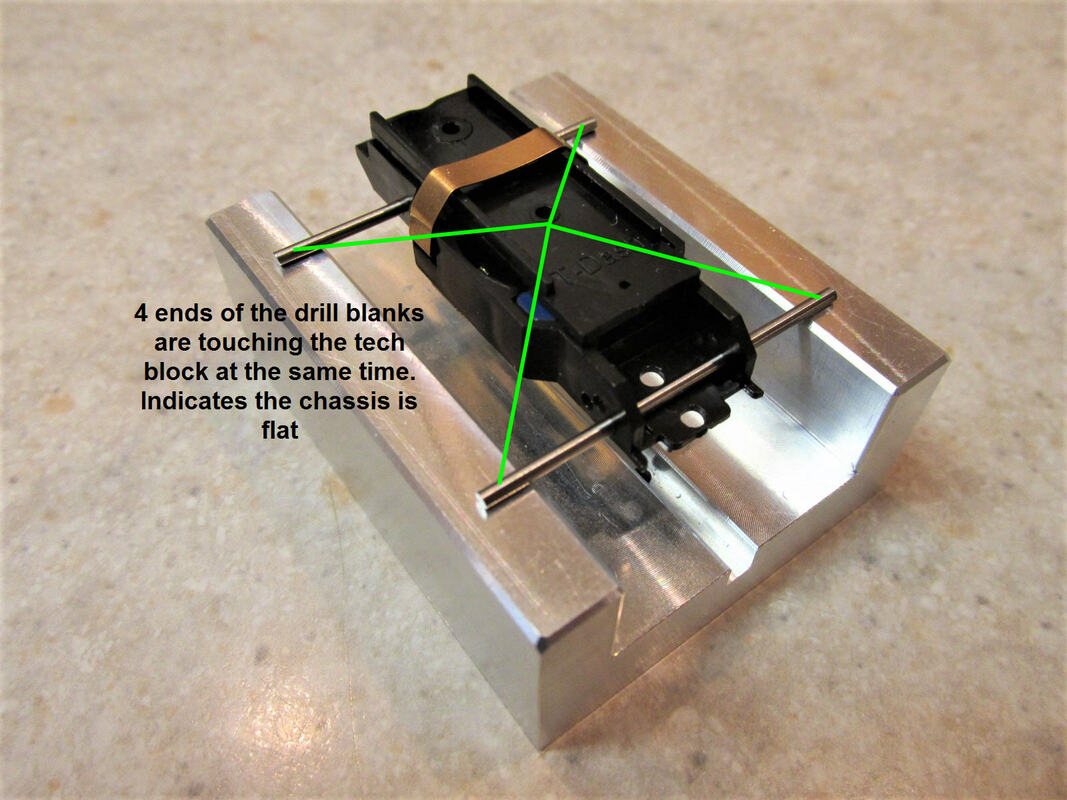
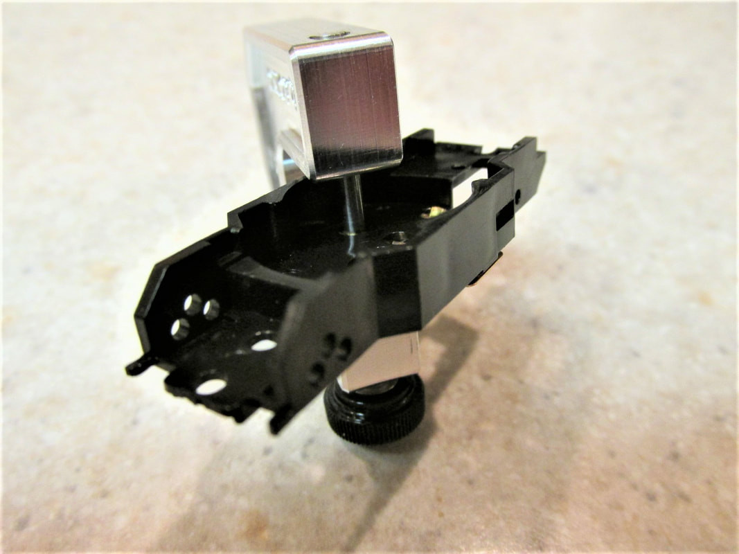
Next I check the the chassis for flatness. The great thing about the Dash chassis is they are consistently flat. To check this I use a tech block and some drill blanks. I insert the drill blanks through the rear and front axle holes. I then place this on the tech block. If the chassis is flat, the 4 ends of the drill blanks will be touching the tech block. Note that when checking for flatness the chassis is checked with the magnets installed.
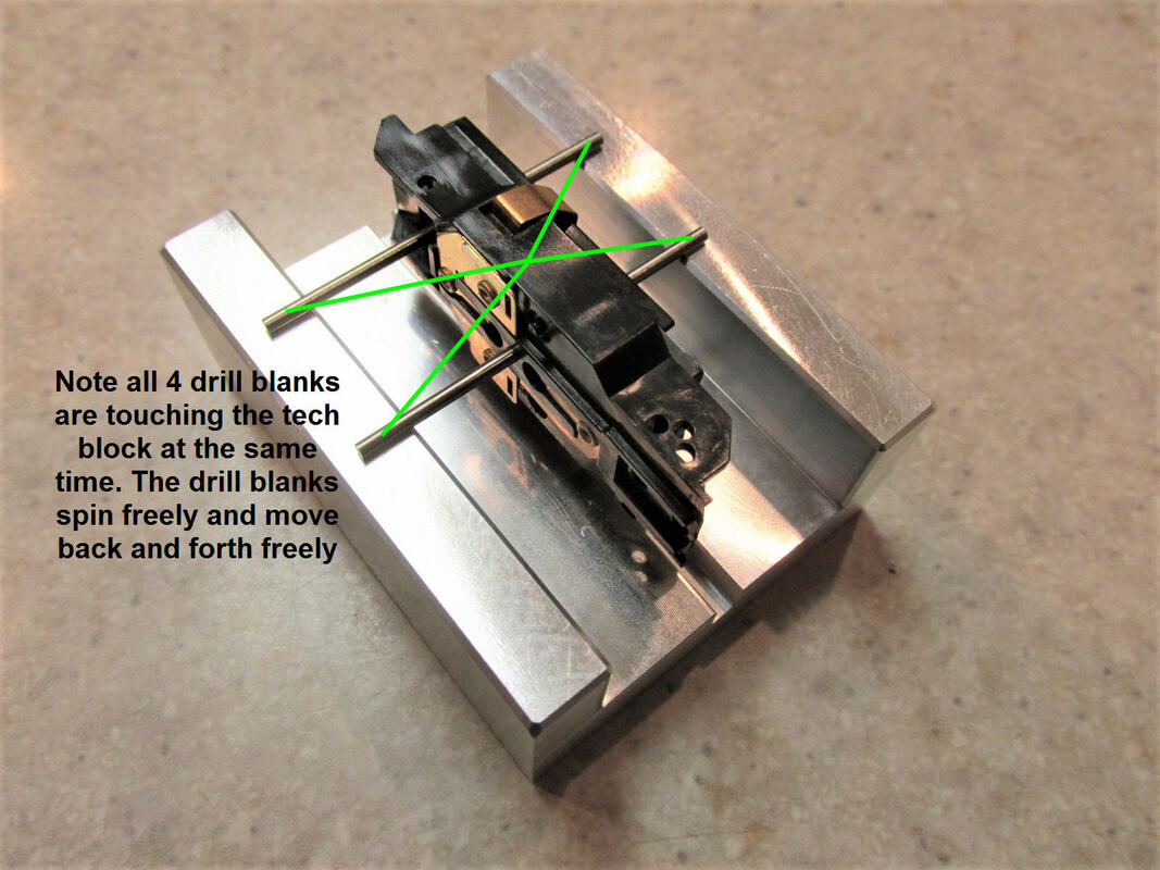
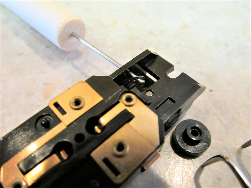
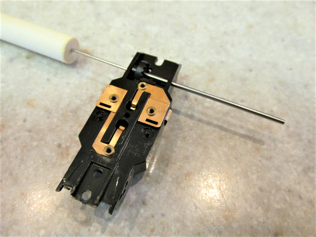
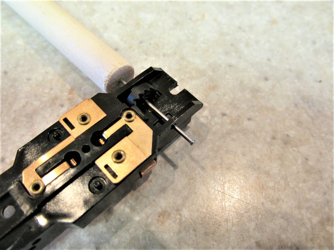
Now I check the chassis and the gear plate. What I am checking here is the armature hole and the driven gear hole matches up between the chassis and gear plate. Again these Dash chassis seem to be consistent here also. And again I will use two drill blanks and a tech block. You attach the gear plate to the chassis and insert the drill blanks into the bottom of the chassis up thru the gear plate. When doing this you should notice a couple of things... the drill blank finds the matching hole and once the drill blank is thru both holes spin it. Is should spin and move back and forth freely. Now lay the chassis sideways on the tech block again all 4 corners should be touching the tech block at the same time. If the chassis and the plate pass these tests I consider them a match.
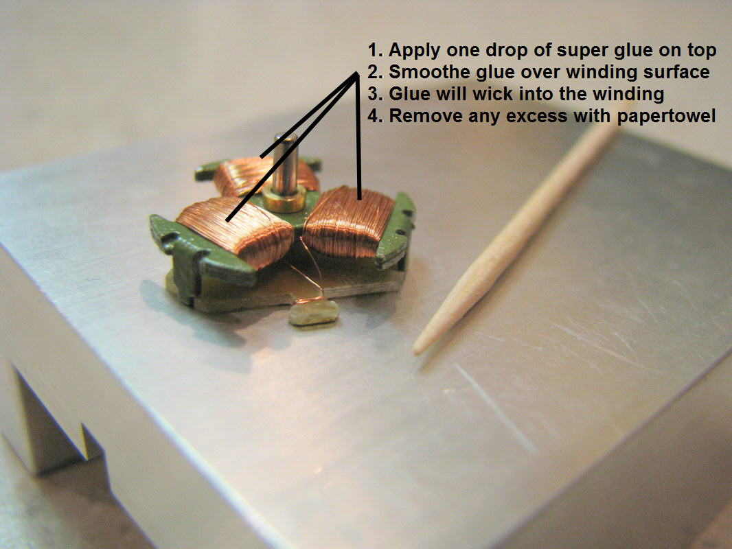
On a rare occasion the Dash armature will start throwing the windings. So as a precaution I use a drop of super glue on top of the winding. If your interested in this topic there is more about thrown windings here.
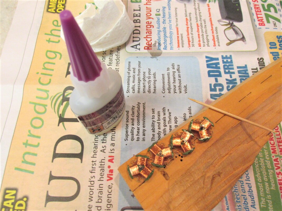
I have used this method on some fray cars and have had hundreds of laps without an issue. It involves a toothpick and some super glue. Take a toothpick and put some super glue on it then put one drop on the winding of the armature pole. Using the side of the toothpick gently spread the super glue over the armature pole winding. You will notice the super glue will wick into the winding. If there is any extra glue then take a paper towel and soak up the excess by lightly touching a corner of the paper towel to the excess glue. Now repeat this process on the other two poles of the armature
I have used this method on some fray cars and have had hundreds of laps without an issue. It involves a toothpick and some super glue. Take a toothpick and put some super glue on it then put one drop on the winding of the armature pole. Using the side of the toothpick gently spread the super glue over the armature pole winding. You will notice the super glue will wick into the winding. If there is any extra glue then take a paper towel and soak up the excess by lightly touching a corner of the paper towel to the excess glue. Now repeat this process on the other two poles of the armature
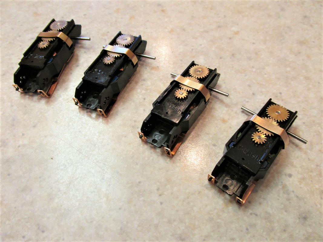
Now repeat the process on the other 3 armatures.
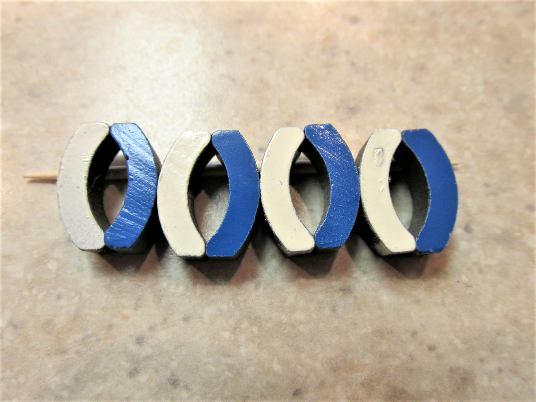
Now let's take a look at the magnets. Given I am only using 4 sets I will use my magnet matcher and get them close. They won't be exact but they will be as close a match as possible. Again this should all come out in the end because each driver will have a turn at driving each car.
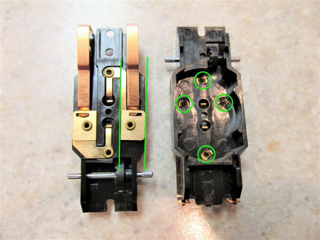
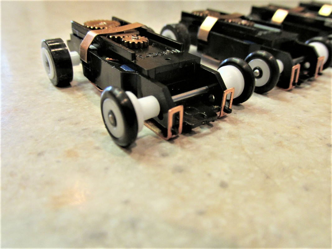
Now let turn our attention back to the chassis. There are a couple of more things to address; the pickup shoe hangers and the chassis rivets. If you look at the picture below you will notice on the left you see the bottom of the chassis. Look closely at the pickup shoe hanger, you'll notice it is not straight. These need to be checked and adjusted before tightening the rivets. Also if you look to the right you will see the inside of the chassis... notice the 4 rivets I will need to clean these up by making sure the rivet material is below the bottom of the chassis when tightening the rivets.
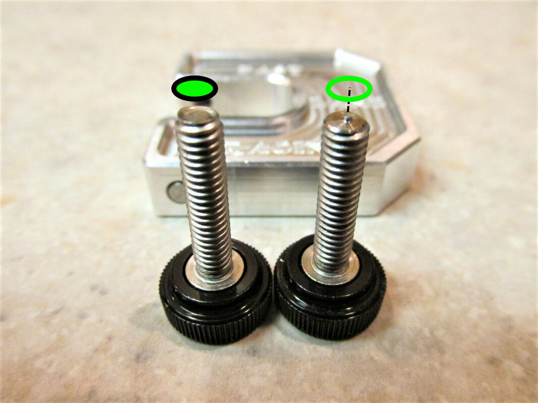
I have a rivet tightening tool made by Fast Lane Racing. You can see more about their products here. Its a pretty good little tool to have It's made with two press tools, one for open rivet and one for solid rivet.
 | 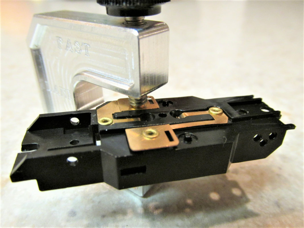 |
Solid rivet press on the left open rivet press on the right.
Next I'll install the new tungsten rear axle and crown gear. The rear gear lash on these are not too bad so it won't take much to shim it out. I have read some discussions on social media that some have started only shimming on one side of the crown gear and let the pinion gear hold the other side of the crown. So I will give that a try on these and see how it works out. So as I indicated earlier it did not take much to shim these crown gears. I only took 1 shim 3 thousandths of an inch thick. (0.003 inch).
So for this I remove the magnets from the chassis, remove the gear plate, insert the pinion gear and clip the gear plate back on. Even though the picture below has the magnets in the chassis remove those magnets it will make this job less frustrating... Also make sure the pinion gear that you used when installing the crown gear stays with the chassis and that crown gear.
Now I use my home made crown gear install tool, pilot rod, and then use a wheel press to install the tungsten axle. If you would like a more in depth explanation on installing a crown gear you can find that here.
  |   |
Bottom of gears polished and installed on the chassis.
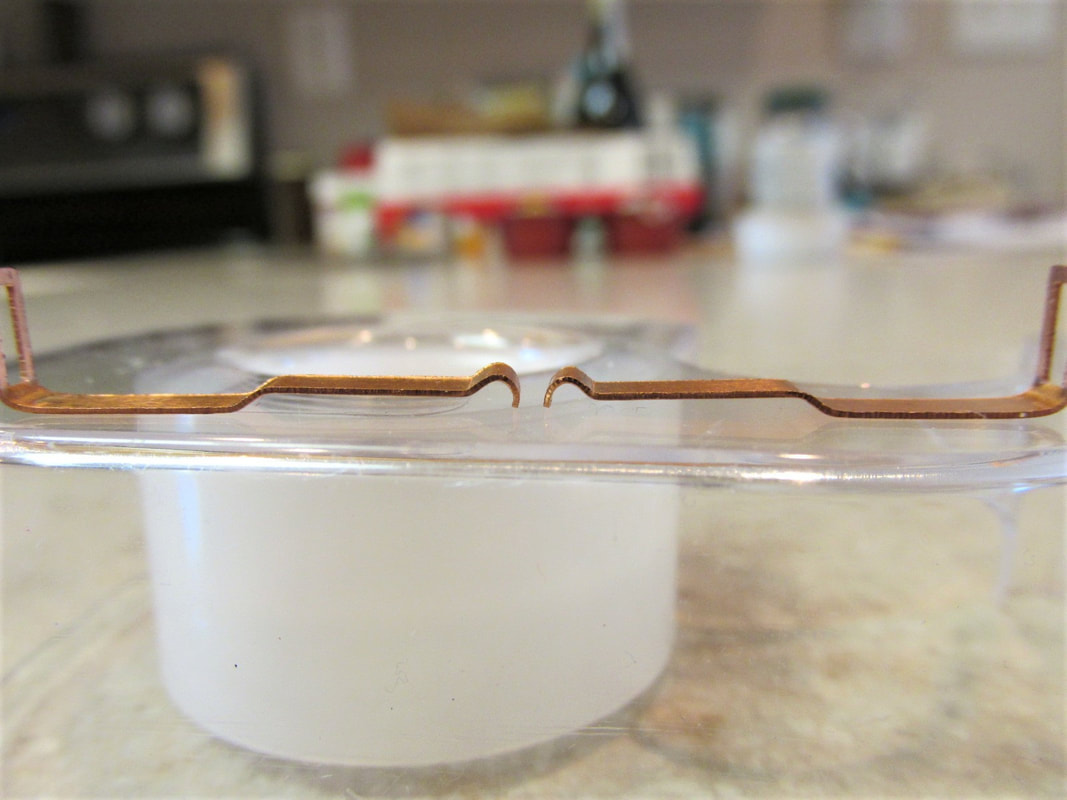
The next adjustment I make is to minimize the front to back travel of the pick-up shoe and create a better contact between the shoe itself and the pick-up shoe hanger. I use my pliers and make a very small bend at the back of the shoe. You can see the difference between the bent and unbent shoe in the picture below. The right shoe is the unbent shoe and the left shoe is the bend one. As you can see the bottom has a ever so slight hook. This helps to keep contact with the shoe hanger on the chassis.
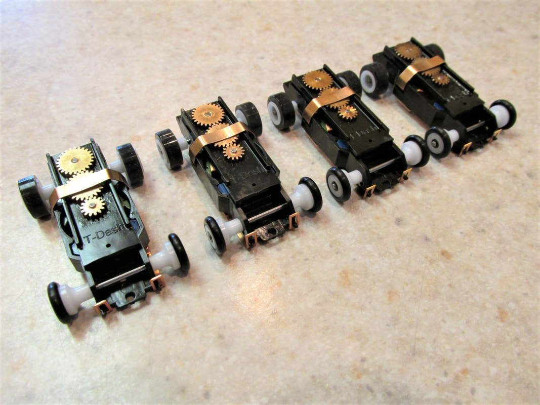
So the next thing was to install the shoes. After that I pressed on the RT-HO indy/hot rod wheels and slip on tires part numbers RT-205 and RT-200.
Then finally installed the RT-HO indy/hot rod front ends part number RT-190
Then I took the chassis and oiled them up and let them run on the break in box.
And now the fun begins adjusting the pick-up shoes and fine tuning the rest of the chassis. As I said earlier in this article I had purchased some Dash hot rod bodies so I finished and painted them up... I think they turned out fairly well. If you would like to see how I finished the bodies you can see the article here.
 RSS Feed