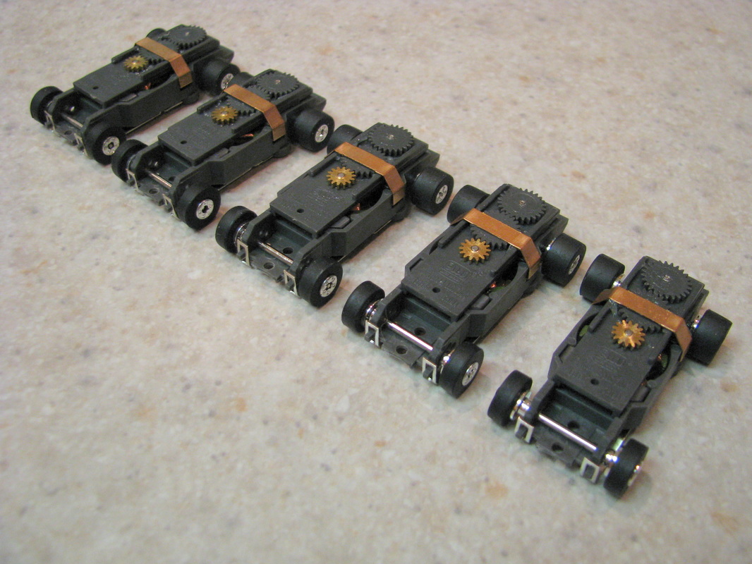
This is the second part of a three part series about the Auto World ThunderJet Ultra-G chassis. In the first part we discussed the out of the box chassis to include visual inspection and measurements taken on individual parts. We then ran the car on the track to establish a baseline with respect to time. You can read part 1 here. In this article we will cherry pick the parts from the 5 cars that were purchased and see what kind of increases we can obtain with this chassis.
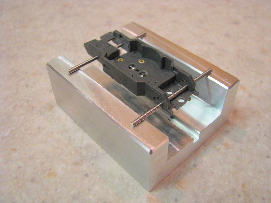
The first thing I will do is start with the chassis. I will check the chassis for flatness and inspect the rivets. When checking the flatness I will use my tech block and drill blanks. If the chassis is not flat it will be rejected.
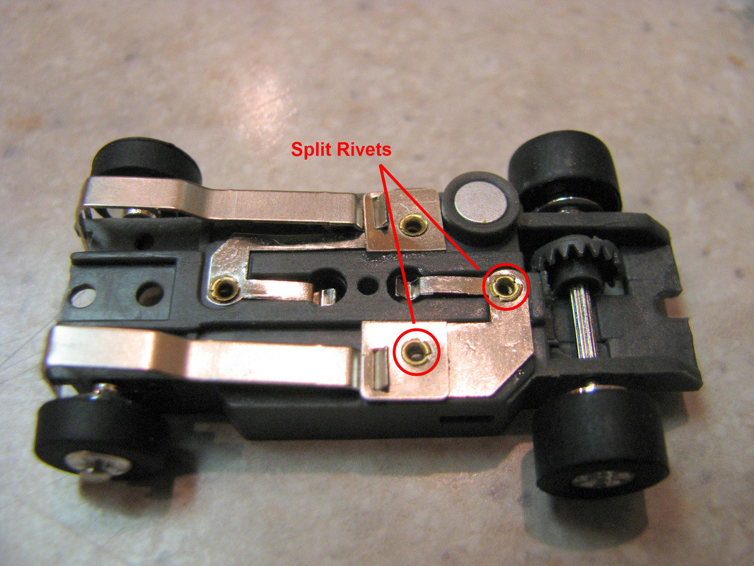
When checking the rivets I will look for splits in the rivets. If I see any splits I will reject the chassis. See the picture below. After further inspection I think the rivets on this chassis were installed upside down.
Next on the list is to cherry pic the magnets. The standard for this was to try and match the magnets as close as possible with respect to strength. Considering I am only dealing with 5 sets of magnets this is about the best I can do.
Now let's take a look at the armatures. I visually inspect them looking for any noticeable physical defects. If none are found then take an Ohm meter and measure each pole and look for the armature that has the lowest ohm readings on the poles and is the closest to being electrically balanced as possible. Electrically balanced is where the ohm readings on the three armature poles are the same. Here's where a little judgement call takes place, trying to balance these two parameters and which parameter takes priority.
Next we will take a look at the axles. Here, I look for straightness. To check this I roll the axles on a flat surface an check for the flatness of the axle with respect to contact on the surface as I roll the axle. If the axle is bent, there will places that the axle will loose contact with the flat surface as you roll the axle with your fingers. If this should happen I will discard the axle.
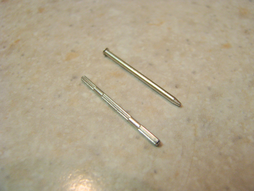
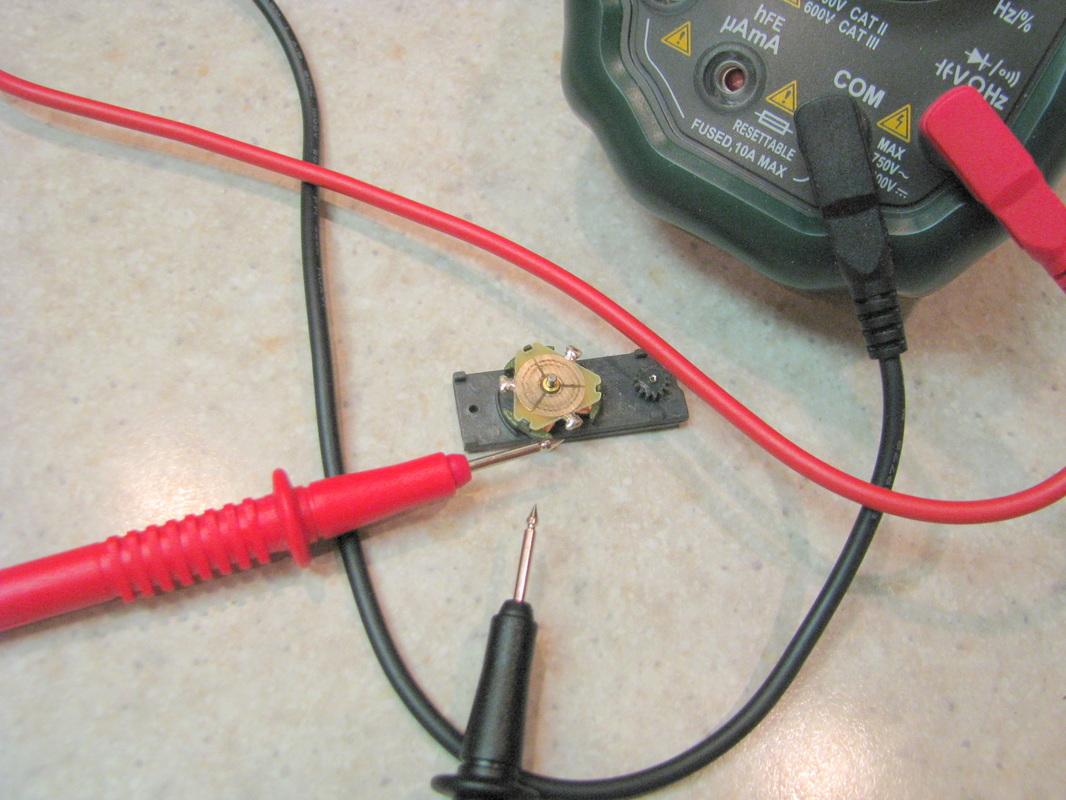
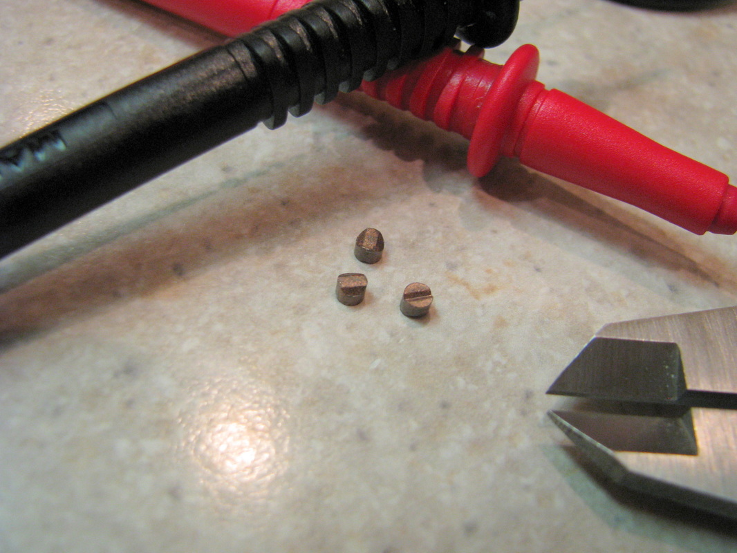
Next up are the commutator brushes. Here I look at three things. The diameter of the brush, the thickness of the brush and the ohm reading of the brush. In part one we determined that Auto World's brushes were pretty consistent. With respect to diameter, I look for the largest diameter that still moves freely in the brush opening. Why the largest diameter. The larger the diameter the more contact surface with the commutator which I think translates to better current flow. With respect to thickness I try to select brushes that have the same thickness. For me this translates more consistency when adjusting the brush springs. I can adjust the springs to be the same on the initial adjustment. Lastly I look for the brush with the lowest ohm reading. Again I think this translates to better current flow.
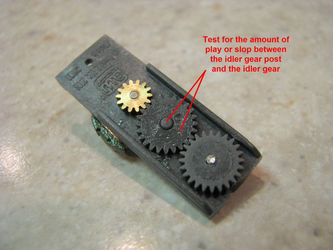
Let's not forget the idler gear. Here, I check for gear play or "slop" between the idler gear and the idler gear post on the gear plate. The gear I choose is the one that meshes well with the other two gears and has the lease amount of "slop".
So after I have "cherry picked" the "better stock parts" for racing, I assemble the chassis, oil it up, and take it for a spin around the track and see what kind of increases we have. The results are on a 37 foot track 13 volts using a 90 ohm controller. Fastest lap was 5.675 seconds the average lap was between 5.7 and 5.8 seconds which is a increase from 5.9 to 6.1 seconds per lap. That's a difference of 1 tenth to 4 tenths of a second difference between laps.
In part three of this series we will take the cherry picked parts and tweek them further and add some speed parts and see what happens. More to come...
 RSS Feed